
Cooling Tower
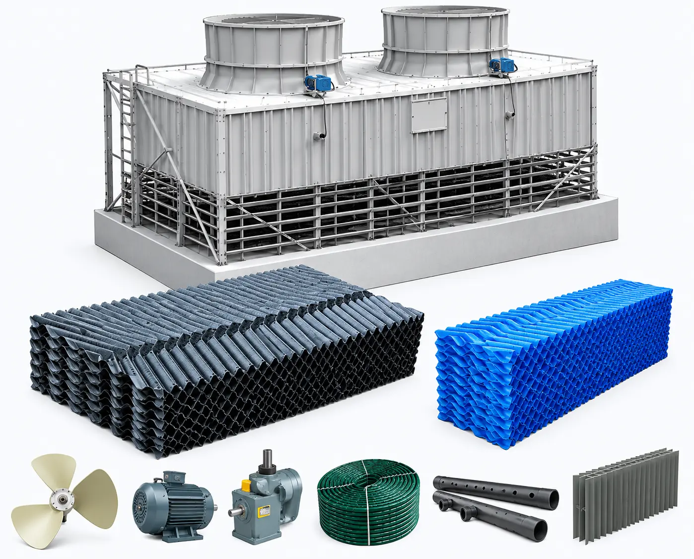
Cooling Towers are used to remove heat from circulating water and are commonly integrated into industrial cooling and process-water systems.
The supplied WRT series provides a wide range of configurations, from WRT-8 through WRT-800, along with NRT-1000. The available models cover different nominal flow rates, tower dimensions, motor power, fan diameters, airflow and water-pressure requirements.
Cooling Tower Components
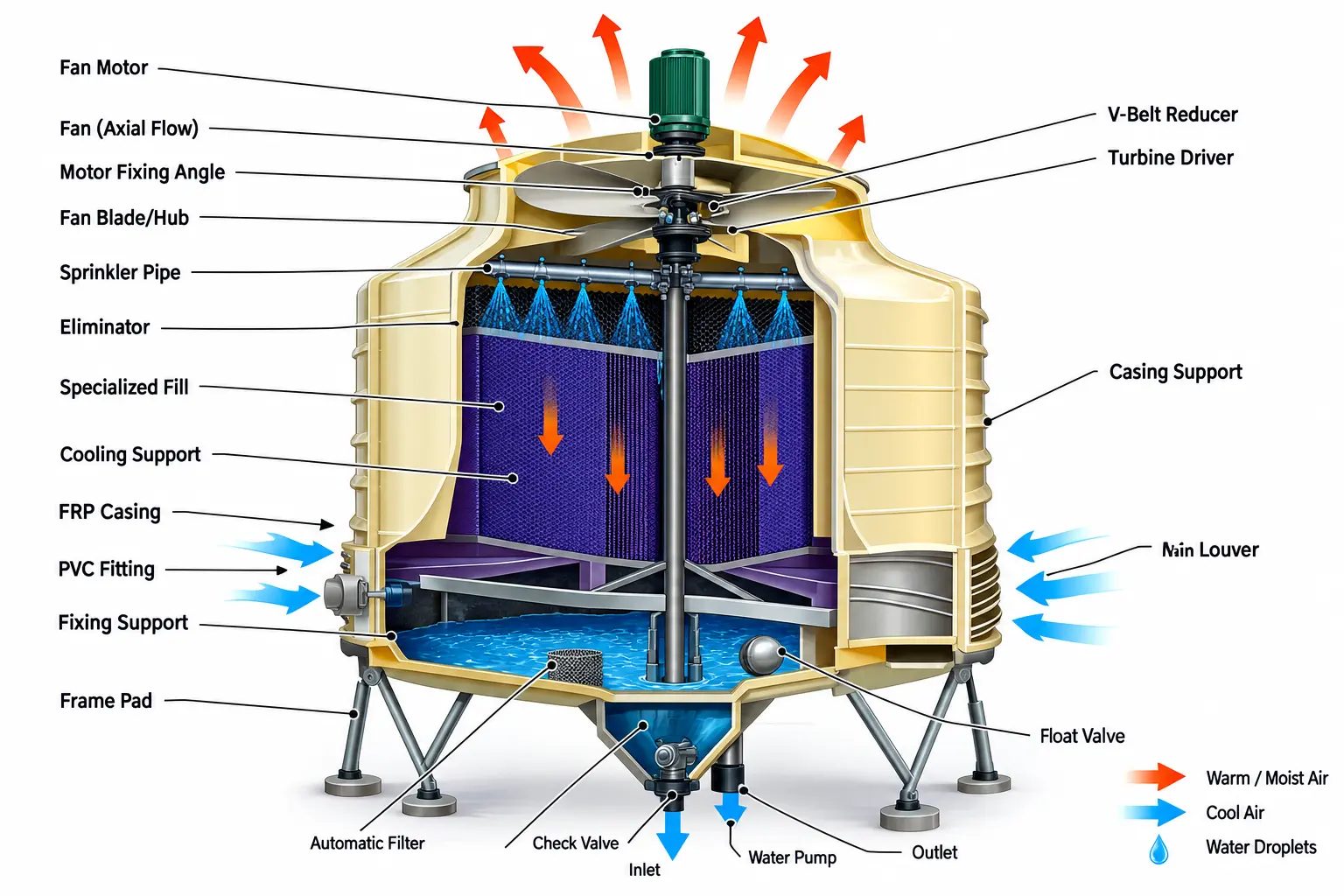
According to the supplied product diagram, the Cooling Tower system includes the following major components:
- Motor (TEFC)
- MS Motor Support
- V-Belt Reducer
- Exhaust Fan
- Fillup
- Sprinkler
- In-Fill Support
- Water Basin (F.R.P)
- Suction Tank
- Piping
- Air Inlet Slant Support
- Eliminator
- Sprinkler Head
- Casing
- Fan Guard
Key Features
- Wide range of cooling tower configurations.
- Multiple nominal flow capacity options.
- Different motor power configurations.
- Multiple fan diameter options.
- Different airflow and water-pressure configurations.
- Available in large-capacity industrial configurations.
- Integrated sprinkler and fill-up system.
- FRP water basin configuration.
- Air inlet and eliminator arrangement.
- Fan guard and casing arrangement.
Technical Specifications
| Model | Nominal Flow (m³/h) | Diameter Max. (mm) | Height (mm) | Motor (kW) | Fan Diam. (mm) | Air Flow (CMM) | Water Pressure (KPa) | Net Weight (kg) | Run. Weight (kg) |
|---|---|---|---|---|---|---|---|---|---|
| WRT-8 | 6.2 | 945 | 1380 | 0.18 | 525 | 70 | 13 | 42 | 180 |
| WRT-10 | 7.8 | 945 | 1530 | 0.18 | 600 | 85 | 13 | 46 | 190 |
| WRT-15 | 11.7 | 1195 | 1415 | 0.37 | 600 | 140 | 13 | 54 | 290 |
| WRT-20 | 15.6 | 1195 | 1590 | 0.55 | 730 | 160 | 14 | 67 | 300 |
| WRT-25 | 19.5 | 1400 | 1820 | 075 | 730 | 200 | 16 | 98 | 500 |
| WRT-30 | 23.4 | 1650 | 1705 | 0.75 | 730 | 230 | 16 | 116 | 530 |
| WRT-40 | 31.2 | 1650 | 1775 | 1.5 | 890 | 280 | 16 | 130 | 550 |
| WRT-50 | 39.2 | 1830 | 1835 | 1.5 | 890 | 330 | 17 | 190 | 975 |
| WRT-60 | 46.8 | 2145 | 1955 | 1.5 | 1150 | 420 | 17 | 240 | 1250 |
| WRT-80 | 62.6 | 2145 | 2035 | 1.5 | 1150 | 450 | 18 | 260 | 1280 |
| WRT-100 | 78.1 | 2900 | 2370 | 2.2 | 1410 | 700 | 21 | 500 | 1690 |
| WRT-125 | 97.5 | 2900 | 2555 | 2.2 | 1410 | 830 | 23 | 540 | 1640 |
| WRT-150 | 117 | 2900 | 2555 | 2.2 | 1410 | 950 | 23 | 580 | 1680 |
| WRT-175 | 136.8 | 3310 | 3165 | 4 | 1750 | 1150 | 30 | 860 | 1960 |
| WRT-200 | 156.2 | 3310 | 3165 | 4 | 1750 | 1250 | 30 | 880 | 1980 |
| WRT-225 | 175.5 | 4120 | 3580 | 5.5 | 2100 | 1500 | 33 | 1050 | 2270 |
| WRT-250 | 195.1 | 4120 | 3580 | 5.5 | 2100 | 1750 | 33 | 1080 | 2800 |
| WRT-300 | 234 | 4730 | 3680 | 7.5 | 2400 | 2000 | 34 | 1760 | 3930 |
| WRT-350 | 273.2 | 4730 | 3680 | 7.5 | 2400 | 2200 | 34 | 1800 | 3790 |
| WRT-400 | 312.1 | 5600 | 3840 | 11 | 2745 | 2400 | 36 | 2840 | 5740 |
| WRT-500 | 392.4 | 5600 | 3840 | 15 | 2745 | 2600 | 36 | 2900 | 3800 |
| WRT-600 | 468 | 6600 | 4470 | 15 | 3400 | 3750 | 42 | 3950 | 9350 |
| WRT-700 | 547.2 | 6600 | 4470 | 18.5 | 3400 | 3750 | 42 | 4050 | 9450 |
| WRT-800 | 626.4 | 7600 | 4720 | 22 | 3700 | 5000 | 45 | 4700 | 11900 |
| NRT-1000 | 781.2 | 7600 | 4720 | 22 | 3700 | 5400 | 45 | 4900 | 12100 |
Cooling Capacity & Flow Range
The supplied Cooling Tower range covers nominal flow capacities from 6.2 m³/h to 781.2 m³/h. The available configurations are designed to accommodate different industrial cooling requirements through a wide range of tower sizes and fan configurations.
Fan & Airflow System
The Cooling Tower models are equipped with different fan diameters and airflow capacities according to the selected configuration. The supplied specification includes fan diameters ranging from 525 mm to 3700 mm and airflow values from 70 CMM to 5400 CMM.
Motor & Drive System
The supplied system diagram identifies a TEFC motor, MS motor support and V-Belt reducer as major components of the Cooling Tower drive arrangement.
Motor power varies across the supplied range from 0.18 kW to 22 kW according to the selected model.
Water Distribution System
The Cooling Tower assembly includes sprinkler, sprinkler head, piping, water basin and suction tank components. These components form part of the water circulation and distribution arrangement shown in the supplied product diagram.
Tower Construction & Components
The supplied Cooling Tower diagram identifies casing, fill-up, in-fill support, eliminator, air inlet slant support and fan guard as part of the tower assembly.
Applications
Cooling Towers are used where circulating water needs to reject heat as part of an industrial or commercial cooling system.
- Industrial process cooling
- Factory cooling systems
- Manufacturing facilities
- Industrial machinery cooling
- Process-water cooling
- Large commercial cooling systems
- Industrial HVAC and cooling applications
Model Selection
The supplied product range includes WRT-8, WRT-10, WRT-15, WRT-20, WRT-25, WRT-30, WRT-40, WRT-50, WRT-60, WRT-80, WRT-100, WRT-125, WRT-150, WRT-175, WRT-200, WRT-225, WRT-250, WRT-300, WRT-350, WRT-400, WRT-500, WRT-600, WRT-700, WRT-800 and NRT-1000.
Selection should consider the required nominal water flow, tower dimensions, motor power, fan diameter, airflow, water pressure and operating weight.
Need an Industrial Cooling Tower?
Contact Master Exhaust House for Cooling Tower specifications, capacity selection, technical guidance and quotation for your industrial cooling project.
Reviews
There are no reviews yet.